
Shanghai chengsi intelligent technology co., LTD
Contact: Mr. Gao
Phone: 17701637746
Phone: 19821311892
Address: no. 265, east street, zhuangxing town, fengxian district, Shanghai
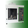
Introduction to glow-wire tester
Glow-wire tester USES simulation technology to evaluate the fire risk caused by thermal stress in a short time by heat source such as searing element or overload resistance. It is suitable for the flammability test and ignition temperature test of electrical equipment, its components and parts, as well as solid electrical insulation materials or other solid combustible materials.
1.1 test principle
1. Fire risk of thermal stress caused by heat sources such as searing elements or overload resistance in a short period of time is evaluated by using simulation technology. 2. The glawing wire is a specified resistance wire ring, which is heated to the specified temperature by electricity, and the top of the glawing wire contacts the sample for a specified period of time to observe and measure the properties of the material. 3. This test device is used for ignition test of non-flame ignition source.
1.2 test standards
The glawing wire tester meets but is not limited to the following standards:
GB/T 5169.10-2006(IEC 60695-2-10:2000); IEC 60695-2-10:20, 13, etc.
1.3 related terms
Test temperature and glawing wire temperature: the top of the glawing wire is heated and reaches a stable temperature before contact with the test sample;
Ignition time: Ti, the duration from the top of the searing wire to the bottom of the test sample or the test sample;
Extinguishing time: Te, the duration from the application of the top of the glow-wire to the flame extinction, during or after the application of flame extinction nuclear energy;
Maximum height of flame: the maximum height of flame after combustion, which is rounded upward in a first gear of 5mm. But at the beginning of kindling, you might have a very high flame, about 1s long, and that flame doesn't count.
Flame generation time: Te, the maximum duration of flame burning with and/or without flame;
Duration of flame and/or flame free combustion of the sample observed after the top of the glowing wire is removed;
Glawing flammability index (glawing flammability index) : the zui high temperature of the tested material measured by the glawing flammability index test method when:
A) failure to burn, or if it starts to burn, it will be extinguished within 30s after removing the glowing wire and not completely burned out; As well as
B) if molten drops are present, they will not ignite the specified wrapping silk paper.
Glow-wire ignition temperature: a temperature 25K(or 30K) higher than the zui high test temperature of the tested material measured by the glow-wire ignition temperature test method when:
A) no fire, or
B) if the duration and continuous combustion time of any one flame does not exceed 5s and the samples are not completely burned.
1.4 composition and use of the instrument

Exhaust fan: exhaust the polluted air through the exhaust fan after the experiment.
Voltage regulator: adjust the temperature of glawing wire by changing the voltage at both ends of the glawing wire by adjusting the voltage regulator knob.

A. gongs: nominal diameter: 4mm; Material: nickel/chromium (80/20) wire; Heating with a simple circuit where there should be no feedback devices or feedback loops to maintain temperature. The typical current required to heat the top to 960 ° c is between 120A and 150A.
B. Temperature measurement -- filament thermocouple: filament thermocouple with first grade mineral insulation metal armor with insulation joints. Nominal diameter shall be 1.0mm or 0.5mm. For example: ni-cr and ni-al (K) wires are suitable for continuous operation at temperatures up to 960℃, with their welding points located within the armor sleeve, as close to the top as possible. Armor sleeves shall be made of metal and shall be able to withstand continuous operation at a temperature of at least 1050℃. Armor sleeves made of nickel base heat resistant alloy are considered to meet the above requirements.
C. Sample carrier: adjustable supporting module, suitable for various standard and non-standard finished products.
D. weight: 0.5n on one side, ensuring that the pressure exerted by searing wire on the sample during the test is 1.0n.
E. Two proximity switches: one is used to detect the starting position of the car, which will stop immediately when the car runs so far. A speed change reminder will slow the car down from 10mm/s-25mm/s to nearly 0 when it passes this position.
F. Baffle: baffle is arranged on the screw rod to push the trolley and stop the trolley from moving. The gap in the bottom of the car allows 7mm of permissible space after the baffle is inserted. When the searing wire touches the sample, the car is no longer pushed by the lead rod, but the car can continue to move as much as 7mm if the searing wire cuts through the sample less under the pull of weight.
G. To assess possible combustion propagation, such as combustion caused by falling from the test sample or by burning particles, a prescribed bed shall be placed under the test sample. Unless otherwise specified, wrap a wrapping silk paper tightly on the top surface of a smooth board of 10mm thickness, and place the hot wire 200±5mm below the point of application of the test sample. Silk paper is a soft and strong lightweight wrapping paper with unit area quality of 12g/m2 -- 30g/m2.
H. Flame height ruler: the flame height ruler is located directly behind the sample at contact with the glowing wire.
I. box requirements: test box that can observe the sample state and has a volume of at least 0.5m2. The volume of the test chamber ensures that the oxygen loss during the test does not significantly affect the test results. The test sample shall be installed at least 100mm away from each surface of the test chamber.
2. The test
2.1 sample preparation:
When the material is tested, the desired shape shall be formed by injection molding, compression molding or compression molding. If this method is not feasible, the sample shall be cut from a representative sample of the material. After the completion of production, use fine sand paper to grind the cut surface smooth, carefully remove all dust and particles on the surface. The sample size should be at least 60mm long and 60mm wide (inside of fixture). Thickness values of xx include: 0.1mm±0.02mm, 0.2mm±0.02mm, 0.4mm±0.05mm, 0.75mm±0.10mm, 1.5mm±0.15mm, 3.0mm± 0.2mm or 6.0mm±0.4mm.
When testing finished products, if possible, the sample should be a complete finished product; If the test cannot be carried out on a complete finished product, you may:
A) cut a piece of the part to be inspected;
B) open a small hole in the complete product to make it contact with the glowing wire;
C) take out the parts to be inspected from the complete finished products and conduct separate tests.
2.2 the power supply
Connect the power cable of the equipment, turn on the power, and turn on the power switch of the equipment.
2.3 test setup
Refer to 3.4 for reference, conduct the test number, set the target temperature to be tested, the application time of searing wire, and the moving speed.
The test number is in full digital form, please do not start with 0, otherwise it will be automatically removed.
2.4 installation of samples and accessories
According to the sample size, adjust the screw distance to fix the sample on the sample carriage. The plane part of the sample is vertical and aligned with the direction of the hot wire.
In the material test, the prescribed bottom layer board and wrapping silk paper shall be placed below the sample, and the height of bottom layer shall be adjusted to 200mm±5mm from the test point.
When the finished product is tested, if 1) when the underlying material representing the material or element around the sample is used, the distance is equal to the actual distance that the sample is installed in the electrical equipment; 2) when complete and independent samples are used, they shall be placed on the prescribed paving layer in the normal use position, and the paving layer shall be extended at least 100mm around the equipment; The test sample is a complete wall-mounted device, placed 200mm±5mm above the specified bottom layer.
2.5 positioning bracket adjustment
Click the motor forward (right) button to make the sample move forward until contact with the scorching wire. Adjust the positioning bracket position so that the cutting line on the positioning plate of the positioning bracket is aligned with the front segment of the trolley positioning plate. Click the motor back button to return the sample carrier to its original position.
Note: repeated adjustments are not required when standard or same-size specimens are continuously tested and materials are installed in the same manner. When the sample thickness is large, observe whether the sample proximity position induction switch can be detected when the sample does not touch the glowing wire. If not, adjust the sample contact position induction switch so that it can be detected before contacting the sample.
2.6 test
heating
The interface automatically displays the sample number set.
Adjust the pressure regulator knob to zero and click the heating button to start heating.
Click the "heat" button, the heating circuit is turned on, and the ginger is heated slowly by manually adjusting the voltage regulator.
Adjust the pressure regulator knob step by step, observe the temperature display meter reading, slowly raise the glawing wire temperature, wait for the glawing wire temperature to reach and stabilize at the set temperature value.
Note: to extend the service life of glawing wire and thermocouple, please slowly increase the heating current.
test
After the searing wire temperature stabilized within the target temperature tolerance range of 60s, the instrument suggested that the test could be carried out.
Click the "start" button to start the experiment.
(at this point, the motor releases the stroke, and the car moves forward along the guide rail under the traction of weight gravity. When the sample is close to the searing wire, the sample trolley speed quickly drops to close and the sample contacts the searing wire. At this time, the baffle piece on the screw rod continues to move for 7mm, and the power of the car is only provided by weight counterweight. The sample is heated, and the interface shows the heating time.
When the sample starts to burn, press the ignition timing button to record the ignition time. When the flame goes out, press the start burning timing button again, and the timing stops.
After waiting for 30s of heating time, the sample carrier will automatically return to the starting induction switch position.
Save the data
Press the "stop" button to automatically save data and turn off the heating current. Turn the regulator to 0 and the glow-wire stops heating.
Turn on the lighting and fan switches. Clean the gills as they cool, if necessary.
Note: it is necessary to clean the glow-wire for cooling, and avoid scalding when cleaning the glow-wire. If the temperature is too low, the solidification of the melted polymer on the surface of the sample may make the cleaning difficult.
Continue to test
If you need to continue the test, go back to the setting interface and input the test parameters, and then reset the test temperature to carry out the test (for example, in the determination of the flammability of the finished product, generally reset the temperature 50℃ higher than the last time to carry out the test again, and the test temperature reaches 60℃ higher than 900℃).
The data view
Click data view to view the test data report. If there is a large amount of data, multiple historical data can be inquired through the drop-down menu.
Note: after the completion of the test, please record the data elsewhere in a timely manner to prevent excessive data from automatically covering the historical data; The maximum data volume of the instrument is 30 pieces.
2.7 end of test
When the experiment is over, ensure that the data have been recorded and adjust the voltage regulator knob on the adjustment panel to 0 scale. Turn on exhaust fan and lighting to clean hot wire surfaces. When the temperature of searing wire drops to normal temperature, turn off the fan, lighting, power and clean the test box.
3. Maintenance and upkeep
3.1 searing wire test
Before each batch is tested, the top dimension "A" must be measured and recorded after bending the glowing wire. This dimension should be compared with subsequent tests and the glow-wire should be replaced when the dimension is reduced to 90% of the initial reading;

At the end of each test, all remnants of material from the top of the glawing wire must be removed if necessary, such as with a wire brush, and then the top of the glawing wire must be inspected for cracks.
3.2 replace the searing wire and thermocouple
If the glow-wire and thermocouple are damaged or one of them is damaged, please replace a set of 1.0mm or 0.5mm glow-wire and matching thermocouple in time.
Replacement: first turn off the power; Loosen the glow-wire fastening screw and remove the glow-wire; Loosen the thermocouple fastening screw, open the side cabinet, remove the thermocouple electrode; Install the gower wire and tighten it to ensure that the gower wire extends 70mm; Install and tighten the thermocouple, and put the thermocouple tip into the hole of hot wire tip; The thermocouple wires are fed into the side case and thermocouple electrodes are installed at the no. 9 and no. 10 electrodes of the temperature control meter.
3.3 calibration of temperature system
Calibration of the temperature system (thermocouple drift) is required when a new thermocouple or searing wire is in use for a long cumulative period. A random password is required for calibration. The default password is "123456" and cannot be modified. Press "reset" to reset the ammeter drift.
Place the calibration silver foil on the top surface of the glowing wire. Refer to part 3.5 of the interface and click "heat" to heat at a suitable low rate. Observe whether the thermometer shows 960℃±15℃ when the silver begins to melt. If so, verify. If not, when silver foil melting is observed, press the "calibration" button to calibrate and calibrate the temperature. Press "end" to disconnect the heating current.
Note: please calibrate within 960±100℃ as shown in the thermometer. Generally, the offset of thermocouple is very small. If the thermocouple is out of range, it means that the thermocouple has failed and needs to be replaced in time. If you need further assistance, please contact the technical department of xx company.
3.4 common problems
1. When the sample carrier is about to contact the scorching wire, and the sample carrier does not slow down, quickly press the "emergency stop" button on the panel to check whether the proximity sensor switch is damaged or whether the proximity sensor position switch is sensitive to the sample carrier (when the sensor switch is on red light, it is sensitive);
2. When the sample carrier touches the scorching wire, the heating time is not timed. Check whether the contact position induction switch is damaged or whether the contact position induction switch detects the sample carrier (the red light of the induction switch is detected);
3. If the sample carrier does not stop when it returns to the starting position sensor switch, quickly press the "emergency stop" button on the panel to check whether the starting position sensor switch is damaged or whether the starting position sensor switch detects the sample carrier (the red light of the sensor switch is detected);
4. Heating current cannot appear all the time. Please check whether the resistance wire of the voltage regulator is burnt out first. If it cannot be solved, please check whether the circuit is broken, xx company requests assistance.
The appendix
The heating temperature of glawing wire corresponds to the reference current. Due to the uncertainty of glawing material and processed material, the specific heating current is around ±5A.
Heating temperature (℃) reference current (A)
50060
55066
60073
65081
70089
75097
800107
850116
900126
960138
Shanghai chengsi intelligent technology co., LTD
Contact: Mr. Gao
Phone: 17701637746
Phone: 19821311892
Address: no. 265, east street, zhuangxing town, fengxian district, Shanghai