
Shanghai chengsi intelligent technology co., LTD
Contact: Mr. Gao
Phone: 17701637746
Phone: 19821311892
Address: no. 265, east street, zhuangxing town, fengxian district, Shanghai
Implementation standard of double plate thermal conductivity tester:
GB/ t10294-2008 determination of steady state thermal resistance and related characteristics of thermal insulation materials
Product introduction
Thermal conductivity is an important parameter used to measure the thermal conductivity and thermal insulation performance of heat-resistant materials. The thermal conductivity of heat-resistant and thermal insulation materials is determined by the thermal conductivity of materials. The computer interface is used to realize automatic control of the instrument, data acquisition and processing, as well as the calculation, display and printing of thermal conductivity. The measurement time is short, the speed is fast, the data is accurate, the degree of automation is high, the noise is low.
The thermal conductivity tester is mainly used to test flat materials such as plastic, rubber, glass, fibreboard, benzene board, extruded plastic board, foamed concrete, hollow glass, wood board, various insulation materials, and can also measure the thermal conductivity of granular materials, bulk materials, soft materials and other materials.
The instrument can be widely used in heat resistant and insulation materials production enterprises, related quality inspection departments and units, institutions of higher learning and research institutes and other scientific research institutions.
I. safety instructions
1. Add liquid medium into the constant temperature tank to immerse the evaporator tube in the medium. The liquid level is lower than the working table and higher than the internal evaporator tube. In use, the medium will slowly volatilize to lower the liquid level, when the liquid level is lower than the evaporator tube, the medium should be added in time, especially attention should be paid to, the medium inside the tank circulates into the container requiring constant temperature will lower the liquid level in the tank, so that the evaporator tube is exposed to the liquid level, at this time, the liquid should be added to immerse the evaporator tube in the medium. No liquid medium is allowed in the tank.
2. The test box shall be placed in the vertical direction during the test, and the card slot of the test box shall not be too tight, so as to facilitate the next operation.
3. The selection of liquid medium in the tank should conform to the following principles:
1) choose antifreeze as the general liquid medium;
2) when the operating temperature is (85 ~ 95)℃, 15% glycerol solution can be used as the liquid medium;
4. Do low temperature test with alcohol to prevent open fire, so as not to cause constant temperature tank combustion.
5. Do not immerse the low-temperature thermostat in water. Otherwise, it may cause a short circuit or electric shock.
6. Do not tilt or invert the test box. In order to ensure the accuracy of the measurement data, the instrument should be in the place of quiet wind and light, and avoid air conditioning and heating equipment.
7. It is necessary to pay attention to the specimen compression, so as not to affect the test accuracy by excessive compression. After the thickness measurement of specimen is completed, please turn off the power of thickness gauge.
8. During the test, do not use the test computer for other work, and do not delete or change the name of files and directories created by the company, otherwise the software may not run.
9. During the test, please arrange a person to watch. In case of any accident, please quit the test immediately and turn off the power of the main engine.
10. Do not disassemble, repair or modify yourself. It may cause fire, electric shock or injury. When you need to repair, please consult with our customer service. Do not put metal objects such as nails or needles in the gaps. Otherwise, electric shock or injury may result.
11. Do not use power other than 220V. The use of a power source other than 220V, or the use of the same socket as other electrical appliances, or the use of unauthorized modification of the power line, may cause fire or electric shock hazards.
12. Do not move the instrument during the test, or the test data may be inaccurate.
13. When dust accumulates on the insertion area of the power cord plug, clean it with a dry cloth. Otherwise it could cause a fire.
14. When pulling out the power cord plug, do not pull the wire, but take the front end of the power plug to directly pull out. Otherwise it may cause electric shock or short circuit and cause fire.
15. Do not turn the thermostat upside down, or it will damage the internal parts.
16. When the operating temperature of the constant temperature tank drops from 60 ° c to 15 ° c, do not immediately start the compressor to cool down the constant temperature tank. The liquid in the constant temperature tank must be replaced or the liquid temperature in the constant temperature tank must be reduced to room temperature before starting refrigeration again.
Unpacking inspection
A packing list is attached to the bulk package of each equipment. Please check each component according to the packing list. If you find any parts missing or damaged, please contact the relevant departments of our company in time, we will deal with it properly for you. (in case of any damage, please keep the certificate as soon as possible.)
Iv. Technical indicators
Technical parameters are as follows:
Table 4-1 technical parameters
Thermal conductivity measurement display range (0.001 -- 2.000)W/ (m•K)
Thermal conductivity measurement accuracy ±3%
Thermal conductivity measurement repeatability ±1%
Temperature measuring range (-5 -- 95)℃
Temperature resolution: 0.01℃
Accuracy of temperature control 0.05℃
Specimen thickness standard is 25mm, range (5 -- 40)mm
1) the thermal resistance of the specimen should not be less than 0.1 (m2•K)/ W;
2) the lower limit of thermal resistance of specimens can be as low as 0.02(m2•K)/ W, but the accuracy of equipment description may not be reached in the whole range.
The size of the specimen is 300mm×300mm
The flatness of specimen is 0.1 mm
Laboratory temperature (15 -- 30)℃, standard temperature (23±2)℃
Laboratory humidity (20 -- 80)%RH, standard humidity (40 -- 60)%RH
Power supply AC 220V±10%, 2.5KW
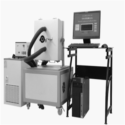
Five, shape and structure
The external structure of the double-plate thermal conductivity tester is shown in figure 5-1 and 5-2:

5-2 protection double plate structure drawing
Vi. Structure composition
Outline and structure diagram of imdry3001-ii double plate thermal conductivity tester, FIG. 6-1; Plan of the double plate thermal conductivity apparatus, FIG. 6-2; The structure of the low-temperature thermostat tank is shown in figure 6-3, and the interface of the low-temperature thermostat tank is shown in figure 6-4.

Figure 6-1 schematic diagram of the external structure of the thermal conductivity apparatus

FIG. 6-2 structure plan
Main heating plate: also known as main heating furnace, diameter of 150mm, internal heater, is the basic heating body of the instrument. Heat is supplied to the specimen. There are two temperature sensors inside the main heating plate -- main board thermometer 1 and main board thermometer 2, which are used to measure the temperature of the hot plate. The precision of the temperature sensor is very high.
Heating plate: external size is 300×300(mm2), internal annular diameter is 152mm. The temperature of the heating plate can track the temperature change of the main heating plate at any time. Its function is to make the heat exchange between the hot plate and the outside world on the one hand, and to ensure that no heat is transferred to the main heating plate on the other hand. Ensure that the heat flow of the main heating plate and cold plate unidirectional flow. There are two high precision temperature sensors inside the guard plate -- guard thermometer 1 and guard thermometer 2, which are used to measure the guard plate temperature.
Cold plate: its size is 300×300(mm2), with annular channel, heating or cooling through a constant temperature tank. The internal temperature sensor is used to measure the temperature of the cold plate.
4 -- specimen: two pieces, 300mm ×300mm, with a standard thickness of 20mm and a maximum size of no more than 50mm. They are placed between the main board cold plates to measure the heat transfer under steady state conditions, and the thermal conductivity of the specimen is calculated.

1 -- operation interface; 2 - circulating pump; 3 - outlet pipe; 4 - water inlet pipe; 5 - cover;
6 -- tank of constant temperature tank; 7 -- pt100 sensor; 8 -- electric heater; 9 -- heat insulation layer;
10 -- refrigeration department; 11 - foot; 12 -- drain valve; 13 -- cooling plate.
FIG. 6-3 schematic diagram of constant temperature tank structure

1 -- PV display (red), showing the measured value or different prompts according to the instrument state;
2 -- SP display (green), displaying set value or different prompt according to instrument state;
3 -- indicator light, self-setting indicator light (AT)(green), heating control indicator light (OUT)(green), alarm output indicator light (ALM)(red); 4 -- number key (liter); 5 -- number key (drop); 6 -- power switch;
7 -- refrigeration switch; 8 -- function key, correction and confirmation of set value; 9 - cycle switch.
FIG. 6-4 interface of low-temperature thermostat
Vii. Working principle
The steady-state measurement is adopted by the imdry3001-ii dual-plate thermal conductivity tester. Only when the cold plate, hot plate and protective plate reach the steady-state thermal balance, can the correct results be obtained. According to the one-dimensional steady-state heat transfer equation, the heat generated by the hot plate heater is transferred to the cold plate through the specimen, and the circulating liquid and other working substances of the cold plate are transferred to the outside of the system, forming a thermodynamic cycle. The thermodynamic equation of the cycle is as follows:


Where: R -- thermal resistance, unit (m2•K)/ W;
Lambda -- thermal conductivity, unit W/ m•K;
Φ - heating unit measurement part of the average heating power, unit in watts (W);
D -- average thickness of specimens in meters (m);
T1 -- the average temperature of the hot surface of the specimen, in unit of open (K);
T2 -- average cold surface temperature of specimens, unit is open (K);
A -- measuring area in square meters (m2).
Eight, operating instructions
(I) test preparation
★ please add the required liquid to the full condition in the constant temperature tank. If not used for a long time, please remove the liquid from the constant temperature tank.
Store in dry condition. Under normal circumstances, the choice of liquid antifreeze.
Requires the use of a stable 220V ac power supply.
★ complete ground line.
★ specimen preparation
The specimen requires 2 pieces of the same material.
The standard size of the specimen is 300×300×(5 ~ 40)mm.
Thickness of specimen (5 ~ 40)mm. Flatness shall be 0.1mm according to the national standard.
In addition, due to different temperatures and humidity in various places, it is recommended that the specimens be maintained before the test.
5. At the same time, the standard substances (also known as standard reference plates) also need to be maintained and kept dry. It is recommended to calibrate the instrument with standard reference plate before each test.
(2) test procedures
1. Specimen placement
★ the host signal line and the computer connection is correct, the computer and the host power plug, open the thermal conductivity machine back power switch;
Put the main furnace body parallel to the ground, insert "fixed bolt" to fix the furnace body;
★ in the state without specimen, rotate the screw handle and return the screw to the lowest position;
★ adjust the thickness ruler to the lowest, open the thickness ruler power switch, press "ZERO" button, make the thickness ruler number is ZERO;
★ rotate the screw handle to return the screw to the highest position;
Open the cover of the furnace and place the test pieces;
★ the specimen is required to be placed flat on the hot plate, note: the specimen should fully contact the hot plate, avoid placing on the fixed plastic around the furnace body, so as not to produce air interlayer, affecting the test results.
★ close the furnace cover, lock the lock, pay attention to the furnace cover and furnace body guard plate grinding;
★ screw the screw handle to make the pressure module number meet the national standard. Do not overcompress the soft specimens.
Adjust the thickness ruler to the minimum, record the thickness ruler number; Note: do not overcompress the soft specimens.
Open the locating bolt, turn the furnace body 180 degrees according to the end of the water pipe, and install the second specimen as above;
Note that the furnace body can only be flipped 180 degrees, do not flip 360 degrees.
Open the locating bolt and put the furnace body on the vertical ground in the test state.
2. Start the experiment
● open the constant temperature tank and set the cold plate temperature (see "use method of constant temperature tank" for details)
Note: please turn on the power switch first, then the cycle switch, and finally the refrigeration switch. Please keep an interval of 3 seconds between each key to avoid excessive instantaneous current. Damage the fuse.
● turn on the computer power switch and enter the main interface of imdry3001-ii thermal conductivity tester; (refer to "(3) software operation" for details)
● click the "enter" button on the left and enter the measurement interface immediately;
● on the left side of the operation interface, input the name of test unit, test person, specimen name and other relevant parameters successively;
● set the hot plate temperature: click the inner box of the hot plate temperature with the mouse, and fill in the required test temperature;
● the thickness of the specimen is the average value of the two measurements in the specimen placement;
● preheating time is generally 30 minutes;
● the test time is generally 150 minutes. Testers can monitor the test process with charts at any time. If the balance cannot be reached for a long time, pay attention to increase the test time accordingly.
3. End of test: when the interface is displayed as shown in figure 8-1 below.

FIG. 8-1 interface at the end of the experiment
● the system will automatically give the test results and test report after the determination. Click "browse all data" in the interface to process and view all data.
● turn off the constant temperature tank (note: please turn off the refrigeration switch first, then the cycle switch, and finally the power switch).
● after the determination, remove the specimen, put it into the protective plate, and put the equipment back in place.
● after printing the data, turn off the power of the computer and the main engine of the heat conductor, and the test is finished.
(3) software operation
1. After installing the specimen, ICONS will be displayed on the computer interface

Click the icon to enter the test interface, as shown in FIG. 8-2.

Figure 8-2 control interface
2. This interface is the "Chinese version" interface.
3. "negotiate with us" : display interface, our company's negotiation method, etc.
4. "about" : click the interface to enter the basic information of the product.
5. "view temperature" : click the interface as shown in FIG. 8-3;

Figure 8-3 shows the temperature
6. "exit" : click to exit the experiment interface.
7. "enter" : click "enter" to enter the test interface, as shown in figure 8-4.

FIG. 8-4 test interface
Each parameter of the test interface is explained as follows:
In the boxes of "input name" and "input parameters", users can input the information accurately before the start of the test according to their own needs and actual conditions, so as to generate the test report. Where "preheating time" is to make the constant temperature tank reach the specified temperature, the total test time = preheating time + test time (the default software time is 120min).
"Real-time display of parameters" : real-time display of the temperature of hot and cold plates during the test.
"Thermal conductivity" : at the beginning of the test, display the thermal conductivity of the test part in real time. Its display process for the warm-up process

,To the beginning of the experiment

,Finally transform to have the data to display

,Real-time display of thermal conductivity.
"Instruction" : enter the instruction code "100", and a dialog box will be displayed in the lower right corner of the test interface

This dialog box contains "hot plate temperature", "guard plate temperature", "cold plate temperature", thermal conductivity and other information. In the instruction, delete instruction code "100", then this dialog box closes automatically. Click "start experiment" to start the experiment. Click "end test" to end the test process.
"Change test time" : after entering the length of time to be changed, click "change" to change the length of test time.
"Correction factor" : due to the irreversible drift and thermal drift of electronic components, the measurement value may be wrong after long use, which needs to be corrected. Click the number box after "correction" with the mouse, input the corresponding coefficient according to the deviation ratio of the data, and click the correction. The factory coefficient is 1.
Determination of correction coefficient:
Lambda is measured three times with the reference plate.
The correction value is calculated as follows:
K = lambda 0 / lambda K '
Lambda 0 -- the standard value for the standard version;
Lambda -- the lambda at test time;
K - correction coefficient input value;
K '-- display value of correction coefficient.
Click the green box under "correction" with the mouse and enter the calculated correction value K, such as 1.02;
Click "correction" with the mouse, immediately complete;
About correction

For example, if the measured data is 10% smaller, we will correct the coefficient. Enter 1.1 in the input field and click "correct". In the display field, 1.1 will be displayed. And the next time we try it, it's still true.
"Test curve" : in this area, the time-temperature curve of each plate can be displayed, among which, red -- hot plate temperature curve, yellow -- protecting plate temperature curve, green -- cold plate temperature curve. The interface also displays "start time", "cumulative time", "total", "remaining", "test time" and other information.
"Function selection" : "click to browse all data" and the interface will appear as shown in figure 8-5:

Figure 8-5 shows the full data
In the "starting serial number", enter the serial number of the data to be queried, and click the "check" button to query the data. "Browse and print current data" means "browse" and "export Excel" for the current test results. Click "exit" to exit the data query interface and enter the main interface of the test.
"Print current data" : the current data can be printed. "Print historical data" enter the historical serial number to query in the column of "serial number", and then "display historical data", "print historical data", "clear historical data", "export Excel" and other data operations can be carried out on the date data.
1) after the start of measurement, if there is no data display or abnormal data display in the real-time display box of the staff in the measurement interface, please immediately exit the test, check whether the power supply of the thermal conductivity machine is on, confirm that it is on, restart the computer and start the test again.
2) in the measurement, if "runtime error '62'" prompt box appears, please click "ok" button to exit the test, then open the power failure recovery folder, copy the files under the folder to the test folder, overwrite the original files, and start the test again.
3) in the test, if the thermal conductivity keeps increasing or decreasing, the test time can be appropriately extended.
9. Use of constant temperature tank
1. Add liquid medium into the tank, the liquid level is lower than the working table and higher than the internal evaporation tube.
2. Connect the inlet and outlet pipes of the circulating pump. Use two hoses to connect the "outlet" to the inlet of the test container outside the tank, and the "inlet" to the outlet of the test container outside the tank.
3. Connect the power, turn on the "power" switch and turn on the "cycle" switch.
Attention! Please keep a 3-second interval between each key to avoid excessive instantaneous current and damage to the fuse.
At this point, PV and SP are initialization states, which are shown as follows:
"Power on" → "upper row display: Sn, lower row display 8" → "upper row display input upper limit, lower row display input lower limit (temperature range display)" → "upper row display measured value, lower row display set value (standard display mode)".
In the above process, all three lights are on, after about 4 seconds of display, automatic conversion is completed, and the standard display mode is entered.
4. Set the temperature
Temperature (SP) shall be set as follows:
"Press function key (8) to enter the setting state"/the upper row displays SP → "press number key (up or down) until the temperature to be set"/the upper row displays SP and the lower row displays setting temperature → "confirm the set temperature and press function key (8)"/the upper row displays the current measured temperature of the constant temperature tank and the lower row displays the setting temperature.
After the above operation, when setting the temperature ≤ the measured temperature, the refrigeration switch shall be turned on, and the instrument shall enter the automatic temperature control state, and the actual temperature in the measurement temperature (PV) display tank shall be measured.
5. Indicator light, function key and number key
1)OUT -- heating control indicator (green);
The OUT indicator is on -- when the measured temperature (PV) is lower than the set temperature (SP), the constant temperature tank is in the heating state;
OUT indicator light is bright and dark alternately -- when the measured temperature (PV) is close to the set temperature (SP), the constant temperature tank is in PID adjustment state;
The OUT indicator is dark -- when the measured temperature (PV) is higher than the set temperature (SP), the constant temperature tank is not heated;
2)ALM -- alarm output indicator light (red)
When the temperature sensor breaks down, the upper row display window displays the error prompt "OVER" symbol, the microcomputer temperature controller automatically turns off the heating controller immediately, the ALM indicator light is on, and the OUT indicator light is dark. When the measured temperature is lower than the set temperature, that is :(PV) -- (SV)≤-3℃, the ALM indicator goes on. At this time, the power should be turned off to check whether the temperature control is out of control.
3)AT -- self-setting indicator (green)
After debugging in the factory, the PID debugging mode has been turned off, so the indicator light does not work.
After pressing 5 for 8 seconds, the AT light will flash, and the meter will start to set itself, and the AT light will go out after setting. A set of PID parameters with faster temperature rise will be obtained, and the meter will be controlled according to the new PID parameters.
After pressing 6 button for 8 seconds, the AT light will flash, and the meter will start to set itself, and the AT light will go out after setting. A set of PID parameters that can overcome over temperature will be obtained, and the meter will be controlled according to the new PID parameters.
H the new PID parameters can be checked on the meter.
In the process of self-setting, press 5 or 6 for 8 seconds and the AT lamp will be off, and the self-setting will be stopped. The instrument will be controlled according to the original PID parameters.
4) function keys -- when a given value is to be set, first press the function keys, then press the digital up and down keys to the temperature to be set, and then press the function keys again. At this time, the number set is valid.

Figure 8-5 shows the full data
In the "starting serial number", enter the serial number of the data to be queried, and click the "check" button to query the data. "Browse and print current data" means "browse" and "export Excel" for the current test results. Click "exit" to exit the data query interface and enter the main interface of the test.
"Print current data" : the current data can be printed. "Print historical data" enter the historical serial number to query in the column of "serial number", and then "display historical data", "print historical data", "clear historical data", "export Excel" and other data operations can be carried out on the date data.
1) after the start of measurement, if there is no data display or abnormal data display in the real-time display box of the staff in the measurement interface, please immediately exit the test, check whether the power supply of the thermal conductivity machine is on, confirm that it is on, restart the computer and start the test again.
2) in the measurement, if "runtime error '62'" prompt box appears, please click "ok" button to exit the test, then open the power failure recovery folder, copy the files under the folder to the test folder, overwrite the original files, and start the test again.
3) in the test, if the thermal conductivity keeps increasing or decreasing, the test time can be appropriately extended.
9. Use of constant temperature tank
1. Add liquid medium into the tank, the liquid level is lower than the working table and higher than the internal evaporation tube.
2. Connect the inlet and outlet pipes of the circulating pump. Use two hoses to connect the "outlet" to the inlet of the test container outside the tank, and the "inlet" to the outlet of the test container outside the tank.
3. Connect the power, turn on the "power" switch and turn on the "cycle" switch.
Attention! Please keep a 3-second interval between each key to avoid excessive instantaneous current and damage to the fuse.
At this point, PV and SP are initialization states, which are shown as follows:
"Power on" → "upper row display: Sn, lower row display 8" → "upper row display input upper limit, lower row display input lower limit (temperature range display)" → "upper row display measured value, lower row display set value (standard display mode)".
In the above process, all three lights are on, after about 4 seconds of display, automatic conversion is completed, and the standard display mode is entered.
4. Set the temperature
Temperature (SP) shall be set as follows:
"Press function key (8) to enter the setting state"/the upper row displays SP → "press number key (up or down) until the temperature to be set"/the upper row displays SP and the lower row displays setting temperature → "confirm the set temperature and press function key (8)"/the upper row displays the current measured temperature of the constant temperature tank and the lower row displays the setting temperature.
After the above operation, when setting the temperature ≤ the measured temperature, the refrigeration switch shall be turned on, and the instrument shall enter the automatic temperature control state, and the actual temperature in the measurement temperature (PV) display tank shall be measured.
5. Indicator light, function key and number key
1)OUT -- heating control indicator (green);
The OUT indicator is on -- when the measured temperature (PV) is lower than the set temperature (SP), the constant temperature tank is in the heating state;
OUT indicator light is bright and dark alternately -- when the measured temperature (PV) is close to the set temperature (SP), the constant temperature tank is in PID adjustment state;
The OUT indicator is dark -- when the measured temperature (PV) is higher than the set temperature (SP), the constant temperature tank is not heated;
2)ALM -- alarm output indicator light (red)
When the temperature sensor breaks down, the upper row display window displays the error prompt "OVER" symbol, the microcomputer temperature controller automatically turns off the heating controller immediately, the ALM indicator light is on, and the OUT indicator light is dark. When the measured temperature is lower than the set temperature, that is :(PV) -- (SV)≤-3℃, the ALM indicator goes on. At this time, the power should be turned off to check whether the temperature control is out of control.
3)AT -- self-setting indicator (green)
After debugging in the factory, the PID debugging mode has been turned off, so the indicator light does not work.
After pressing 5 for 8 seconds, the AT light will flash, and the meter will start to set itself, and the AT light will go out after setting. A set of PID parameters with faster temperature rise will be obtained, and the meter will be controlled according to the new PID parameters.
After pressing 6 button for 8 seconds, the AT light will flash, and the meter will start to set itself, and the AT light will go out after setting. A set of PID parameters that can overcome over temperature will be obtained, and the meter will be controlled according to the new PID parameters.
H the new PID parameters can be checked on the meter.
In the process of self-setting, press 5 or 6 for 8 seconds and the AT lamp will be off, and the self-setting will be stopped. The instrument will be controlled according to the original PID parameters.
4) function keys -- when a given value is to be set, first press the function keys, then press the digital up and down keys to the temperature to be set, and then press the function keys again. At this time, the number set is valid. 5) number key -- there are two Numbers keys. Tap the number key to go up or down one
A word; Hold it down and the number goes up or down.
After the test, turn off the refrigeration switch, then the cycle switch, and finally the main power switch.
X. maintenance and repair
Taken the maintenance
1. If any abnormality is found in the instrument, please stop using it immediately and consult our technical department;
2. The power of the instrument must be turned off when not in use;
3. Avoid moisture, high temperature and strong electromagnetic field when storing the instrument;
4. Please consult relevant technical personnel of the manufacturer for product calibration and maintenance;
5. The corresponding temperature and humidity environment should be matched in the thermal test.
Taken the maintenance
Thank you for trusting the series products of Shanghai qianshi precision electromechanical technology co., LTD. In order to avoid your worries. Shanghai qianshi precision electromechanical technology co., LTD., relying on the faith of "full service", adhering to the service concept of high quality, standard, professional and fast, thanks for your trust in the products of Shanghai qianshi precision electromechanical technology co., LTD.
Our service
1. Technical specialists respond to customers' consultation 24 hours a day and expert hotline to answer various technical questions at any time;
2. Free on-site installation, debugging and technical training;
3. From the date of purchase, the company shall guarantee the product quality for one year and provide all free services;
4. Lifelong maintenance, cost maintenance will be charged outside the warranty period;
5. Intelligent products can also be maintained and repaired free of charge through the network to help solve difficult problems such as software and hardware. Free software updates.
★ this commitment shall not apply to the following situations:
1. The whole machine or parts of this product have exceeded the free repair period;
2. The products have no equipment identification of Shanghai qianshi precision mechanical and electrical technology co., LTD., no factory name, address, date of production or product qualification certificate, or the marks, marks and labels indicating the relevant information of the products have been deleted or erased;
3. Failure or damage caused by failure/error/improper use, storage, maintenance or operation of the product in accordance with the requirements of the manual (such as live plug and unplug data cable, etc.);
4. Failure or damage caused by working conditions other than those specified by the product (such as too high or too low temperature, too wet or dry, electromagnetic interference, unstable power supply, static interference, etc.);
5. Failure or damage caused by installation, repair, alteration, addition or disassembly of an authorized institution or person not authorized by Shanghai qianshi precision mechanical and electrical technology co., LTD.;
6. Failure or damage caused by unexpected factors or human factors (including computer virus, operation error, liquid input, scratch, bump, foreign body entry, rodent damage, insect pest, etc.);
7. Failure or damage caused by natural disasters and other force majeure (such as earthquake, fire, lightning strike, etc.);
Shanghai chengsi intelligent technology co., LTD
Contact: Mr. Gao
Phone: 17701637746
Phone: 19821311892
Address: no. 265, east street, zhuangxing town, fengxian district, Shanghai