
Shanghai chengsi intelligent technology co., LTD
Contact: Mr. Gao
Phone: 17701637746
Phone: 19821311892
Address: no. 265, east street, zhuangxing town, fengxian district, Shanghai
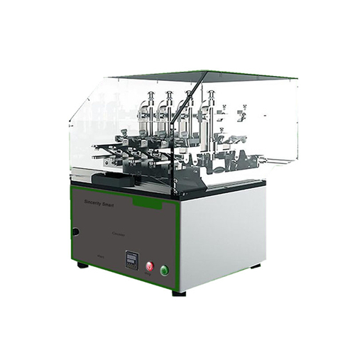

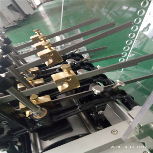
The oscillating cylinder testing machine is used to determine the wear resistance of the fabric when it is rubbed on the standard abrasive or the wire mesh moving back and forth on the curved surface. There is particular interest in fabric manufacturers in the automotive and furniture industries that meet us standards. The motor is driven with 4 wear heads and an electronic digital counter to control the number of cycles.
Item ASTM d4157-02 measurements
Swing radians 76±2 mm
Speed 90±1 /min(double friction)
The weight of 1340 g
The tension applied to the sample can be adjusted from 4.45(1 lb) to 26.7N(6 lb) sample clip ※2 lb2.5 lb3 lb3.5 lb4 lb4.5 lb5 lb
The weight of 2150 g
The pressure applied to the sample can be adjusted from 4.45n (1 lb) to 15.575n (3.5 lb)
Sponge rubber press pad 50×50mm(±1mm)
Other rubber pads and roller seamless
physical
Length :50 cm
Width :50 cm
Height :60 cm
Steel structure:
Finish: print
Weight :75 kg
electricity
220V, 50Hz, maximum 0.05a
1. Install
1.1 turn on the instrument
When you receive your vibration cylinder tester check the carton for possible damage during transportation. Open the instrument carefully and thoroughly check the parts for damage or shortage. Report any equipment damage and/or shortages to honest smart customer service.
1.2 set up
After opening the vibration cylinder tester, place the instrument in a flat and smooth room with constant temperature and humidity.
Insert the power cord into the back of the instrument. Make sure the plug is securely inserted into the instrument.
When the power switch is off, plug the power cord into the appropriate power socket. Proper grounding should be ensured.
5. The operating
5.1 sampling
5.1.1 sampling according to the requirements of applicable material specifications or the agreement between the buyer and the seller. In the absence of such specifications or other protocols, sample as specified in 7.2.
5.1.2 take one laboratory sample from each roll or piece of fabric in the batch. Laboratory samples shall be full-width, at least 50 cm (about 20 inches) long, and shall not exceed 1 m (1 yard) near the ends of rolls or fabrics. Roll or fabric as the main sampling unit.
5.1.3 a laboratory sampling unit shall be taken from each roll or piece of fabric in the batch, with a width of full width and a length of at least 50 cm (20 inches), and the sampling distance shall not exceed 1 m (1 yard) from the end of the roll or piece of fabric.
5.1.4 shipment of clothing samples agreed by buyer and seller.
5.2 quantity and preparation
5.2.1 in the absence of any applicable material specifications, 12 samples of 6 warp (machine direction) and 6 weft (machine direction) from each sample to be tested shall be taken.
5.2.2 sample preparation:
Cut the sample 73 mm (27/8). 245 mm (95 cr 8). Specimens should be cut with fire or wings. Parallel cutting of long dimension and weft is used for rubbing of weft (machine direction) and parallel cutting of weft is used for rubbing of weft (machine direction). You may not cut two warp threads with the same warp or two weft threads with the same weft in woven fabrics. If the fabric has a pattern, make sure the sample is representative of the pattern.
5.2.2.2 cut the sample in the direction of fabric length and width. The samples are cut diagonally across the length and width of the fabric.
5.2.2.3 ensure that the specimen has no wrinkles, creases or wrinkles. Do not take specimens within 10% of the selvage.
5.2.2.4 if the fabric has a pattern, ensure that the sample is representative of the pattern.
5.2.2.5 seal edges when necessary to prevent them from unraveling. The edge of the sample may be sealed with rubber blue or closed with the stitches described in test method d5034.
5.3 the air conditioning
For the test, the specimen was first placed under standard atmospheric pressure to approximately reach the water balance for pretreatment, and then the specimen was placed under standard atmospheric pressure to approximately reach the water balance for the test. When the increase of the weight of the specimen in the continuous weighing for no less than 2 hours is no more than 0.1% of the weight of the specimen, it is considered to have reached equilibrium.
5.4 preparation, maintenance and calibration of test instruments
5.4.1 prepare and verify the calibration of the wear tester using the manufacturer's instructions.
5.4.2 confirm that the rubber pad extends below the support.
5.4.3 confirm that the entire lower surface of the rubber pad is in contact with the cylinder segment without clearance. If space is observed, reshape the underlying surface as instructed. The pads should be replaced at least once a year.
5.4.3.1 if wire mesh grinding agent is used, please use nylon brush to clean it. Clean tank. Insert and clamp 50 sandpaper to cylinder. Remove all pressure from the pad and lock the sample holding arm in place. Run the test program in 50 cycle increments. Check the space between the underside of the pad and the cylinder after every 50 cycles.
Continue until the entire surface of the pad conforms to the shape of the cylinder section. Wear patterns on sandpaper can help determine eligibility.
5.4.4 at least weekly: clean the surface of cylinder segment and steel mesh first, then clean with a mild detergent solution. Remove the vacuum system. Check the wear and polish of gaskets in accordance with the requirements of 10.3.1.
5.4.5 after each test: brush the rubber pad clean and remove any loose fibers. Using a nylon brush, use a cloth to clean the cylinder section surface and steel mesh surface. If using a disposable abrasive, such as sandpaper or cotton duck, replace it after each test.
10.6 the calibration of oscillating cylinder should be carried out according to the appendix of this method.
5.5 the program
5.5.1 test conditions standards atmos for textile products, 70±2°F(21±1°C) and 65±2% relative humidity.
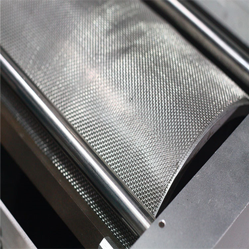
5.5.2 select abrasive for a given end-use application. See table 1. Ensure that the grinding agent is tensed and fully secured to the cylinder. If no abrasive is specified, use steel mesh. If using no. 10 cotton duck, make sure you use a new piece of duck and install it on the machine with the cutting direction parallel to the warp line. If we are using wire mesh, it should be pre-set and should be discarded after 20 million cycles or after visible wear, whichever comes first.
5.5.3 4 warp and 4 unraded stuffed specimens were randomly retained from the laboratory sampling unit as control.
5.5.4 carefully handle samples to avoid changing the natural state of materials.
5.5.5 set the sliding mass on the tension bar to the specified tension for the given end use. See table 1. Set to 8.9n (2 LBF) without specifying tension. Ensure the sliding mass is set to the appropriate tension.
5.5.6 installation method:
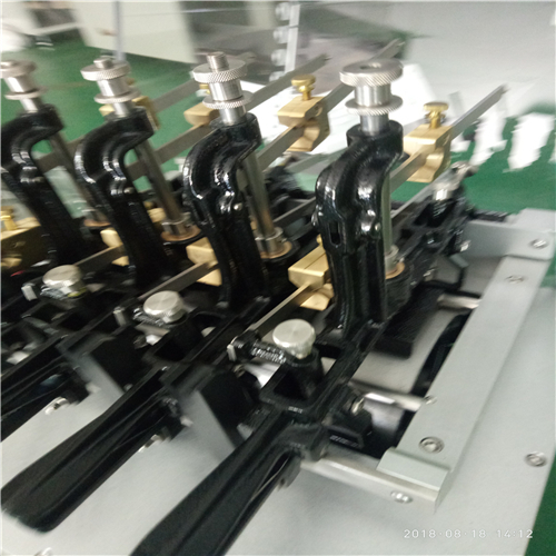
5.5.6.1 option 1 place the sample in a long-dimension single-arm fixture parallel to the direction of wear and place the sample on a fabric surface in contact with the abrasive. The specimen was fixed with a back clip. Clamp the specimen with the front clamp, maintain the same tension in the short direction, tighten the specimen, and pull the weighted tension bar back to the horizontal position. Secure front clip. To ensure even tension on all yarns, use a fixture of at least 1.5 inches to tighten the sample. Broad jaw, perpendicular to its margin.
5.5.6.2 select 2 to fix the specimen in the front clip with the arm upward. Put the specimen through the back clip without tightening. Keep the arms up, push the lever, and adjust the bottom clip. Tighten the back clip with one hand, keeping the fabric in the arm-down position. The tension rod is horizontal and needs to be adjusted slightly.
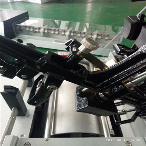
5.5.7 adjust the knurled screw at the top of the arm so that the press bar is in a horizontal position. This position depends on the thickness of the sample. Check with a level.
5.5.8 ensure additional samples on all test arms as indicated in 11.4-11.7.
Set the automatic counter on the grinder to stop at the specified number of cycles. If no number of loops is specified, set to 3000. For longer tests, check every 5,000 cycles.
5.5.10 start the machine and grind the sample to the set number of cycles.
5.5.10.1 if the specimen is stretched during the test, pull the scaled tension bar back to the horizontal position with a level instrument by adjusting the kool screw behind the rear clamp.
5.5.11 grinding 2 samples in longitudinal (longitudinal) direction and 2 samples in zonal (transverse) direction for each cycle. The number of samples specified in the test material specification.
5.5.12 the specimen shall be evaluated according to one or more of the following procedures when it is worn out to a specified number of cycles or other specified end points or faults.
5.6 interpretation of results
5.6.1 wear to fracture -- calculate the average repair cycle of each sample using the following table:
The total number of cycles averaged to the nearest
10 cycles below 200
200 to 1,000, no more than 25
1,000 to 5,000, no more than 50
5000 cycles and over 100 cycles
5.6.2 percentage of fracture load loss - determine the fracture load of wear samples within a specified period by using test method D 5035 and ravel band method. The wear area of the specimen shall be located in the center of the tear zone and placed between the fixture of the tensile testing machine.
5.6.2.1 under the same conditions, determine the fracture load of the uncoated part of the same sample or control fabric.
5.6.2.2 by calculating the fracture load loss, the fracture load of wear specimens was compared with that of control specimens, and formula 1 was used to report the nearest 1.0%:
(1)
Location:
A = fracture load before wear
B = fracture load after wear.
5.6.3 appearance change assessment -- make a visual assessment of the impact of wear on luster, color, fluff, pilling, etc.
5.6.3.1 option 1: the end point is reached when two or more yarns are broken or holes appear in knitted fabrics.
5.6.3.2 option 2 reaches the end point when the color or appearance changes enough to cause customer complaints. Color changes can be caused by a variety of factors, such as the loss of raised finish, the effect of xx rings or fancy yarns.
When different types of fibers are dyed in different ways in an intimate blend, different losses in the yarn or fiber can result in significant color or appearance changes. In this case, the endpoint is evaluated according to the AATCC gray scale of the color change agreed upon by the seller and buyer.
5.6.3.3 when the evaluation shadow changes to AATCC gray level 3 or lower, the end point is reached.
Shanghai chengsi intelligent technology co., LTD
Contact: Mr. Gao
Phone: 17701637746
Phone: 19821311892
Address: no. 265, east street, zhuangxing town, fengxian district, Shanghai